White paper
Dispensing Solder Paste on Factory-Fabricated PCBs
Printed circuit boards (PCBs) are essential for electronic circuits, providing mechanical support and electrical connections for components. Factory fabricated (or sometimes called prefabricated) PCBs are pre-manufactured, ready-to-use boards that simplify assembly and ensure consistent quality in electronic devices.

- Voltera T4 Solder Paste
- Voltera V-One
- Factory fabricated PCB (FR4)
- V-One PCB printer
- Tweezers
- Clamps
- Thumb screws
- Disposable nozzles
Video
Project Overview
Purpose
The purpose of this project was to demonstrate the feasibility of dispensing solder paste on factory fabricated PCBs precisely and reflowing the solder paste automatically.
Design
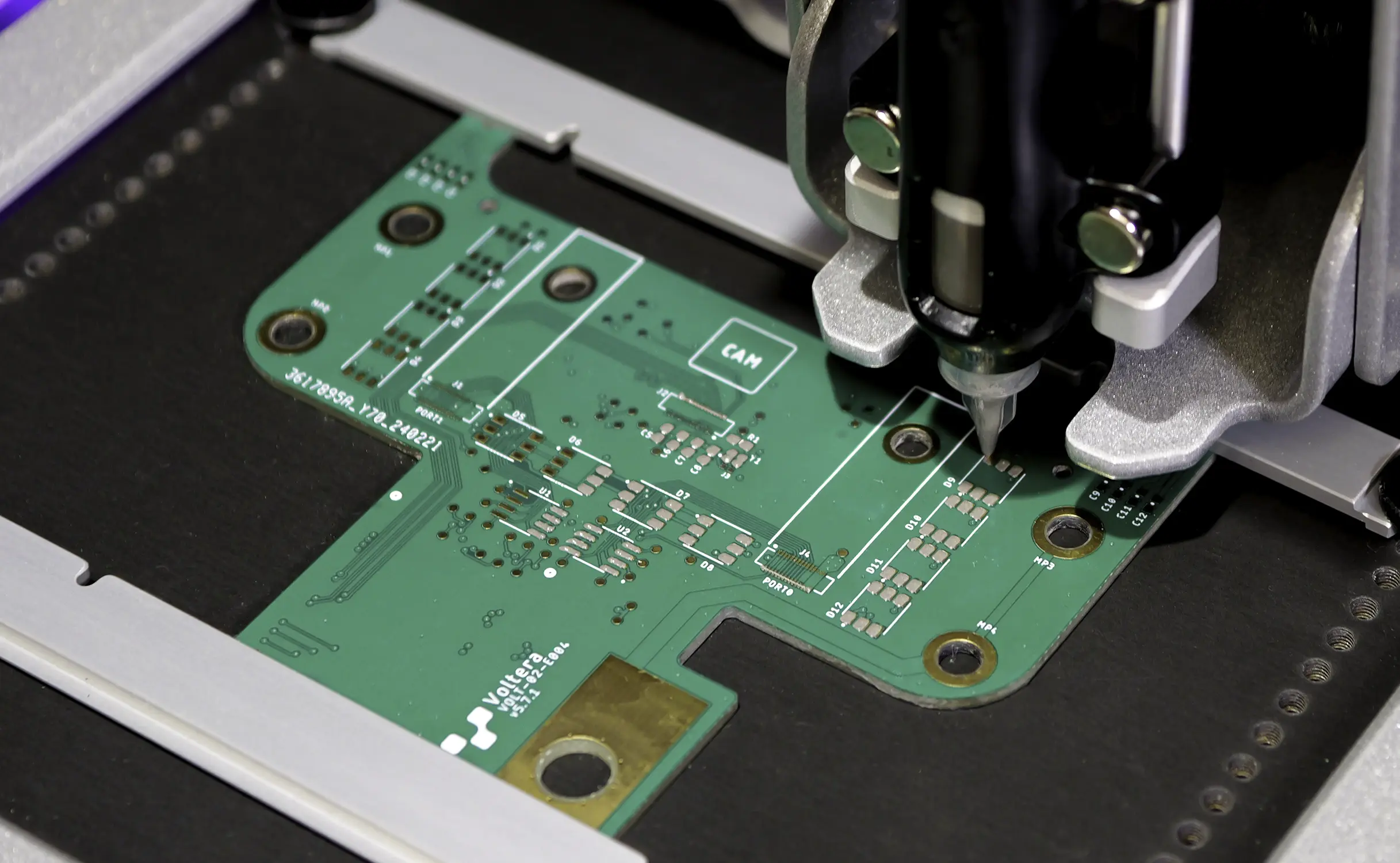
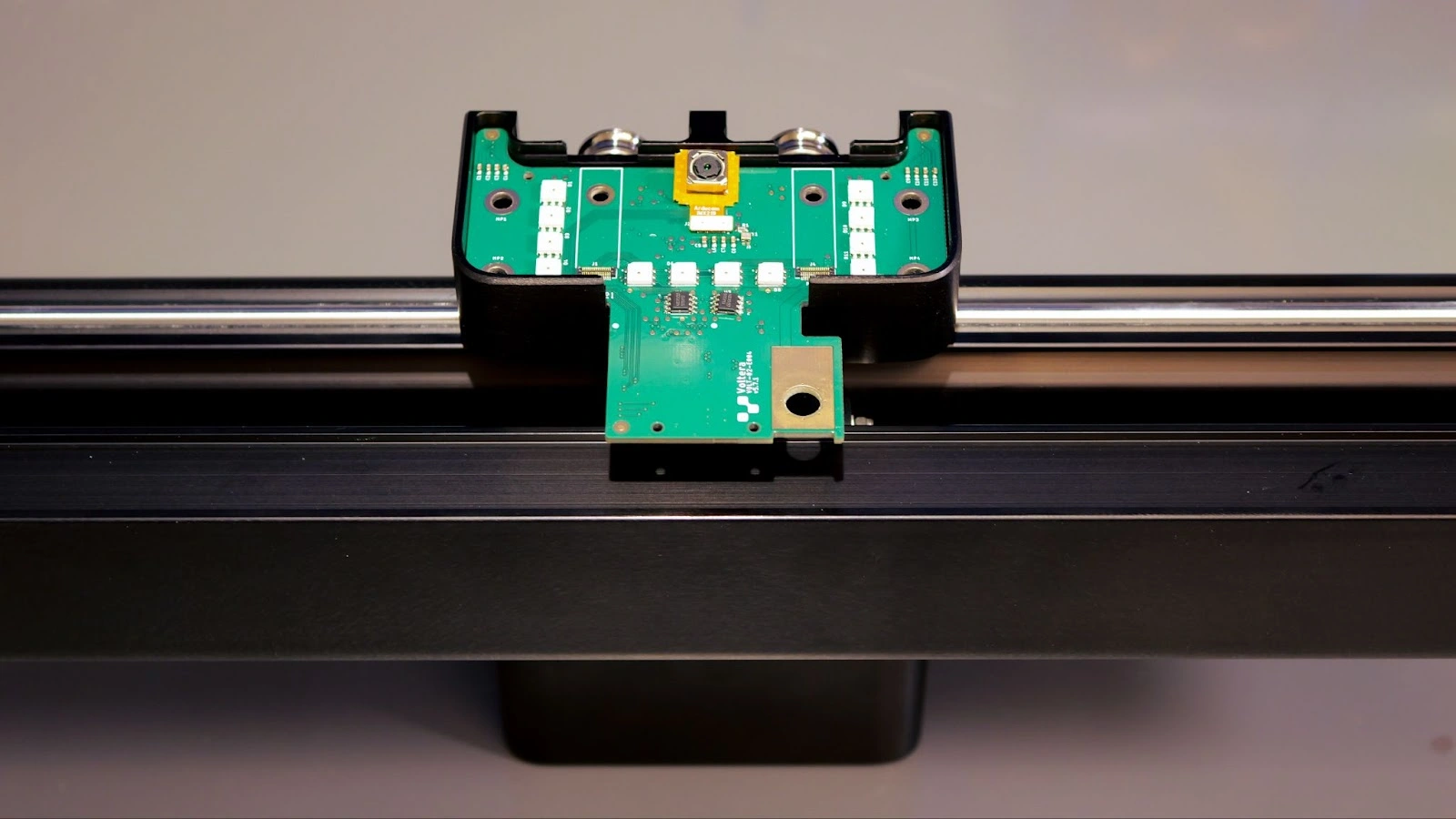
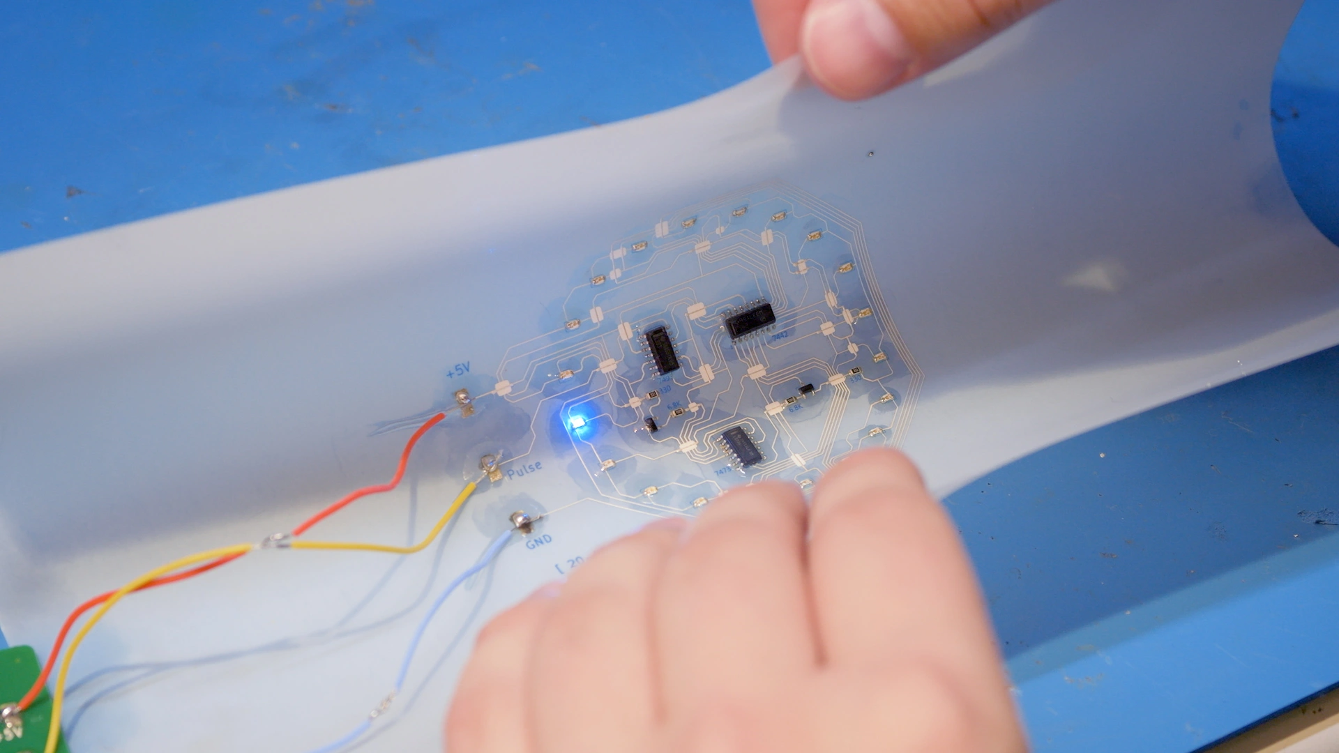
The board we selected for this project was a PCB used in the module hub of our NOVA material dispensing system. Since we designed the board in-house, we had the Gerber file for this project, which we uploaded into V-One’s software.
Desired outcome
The solder paste should be evenly dispensed on the designated spots of the FR4 board, with no overflow or voids. Once reflowed, the PCB should fit into the bottom of NOVA’s module hub. When connected to power, this board will allow NOVA to capture images of its work area.
Functionality
The PCB contains a camera, LEDs, and other components that enable NOVA to capture images of the printed traces and pads, facilitating examination and ensuring optimal alignment.
Preparing V-One
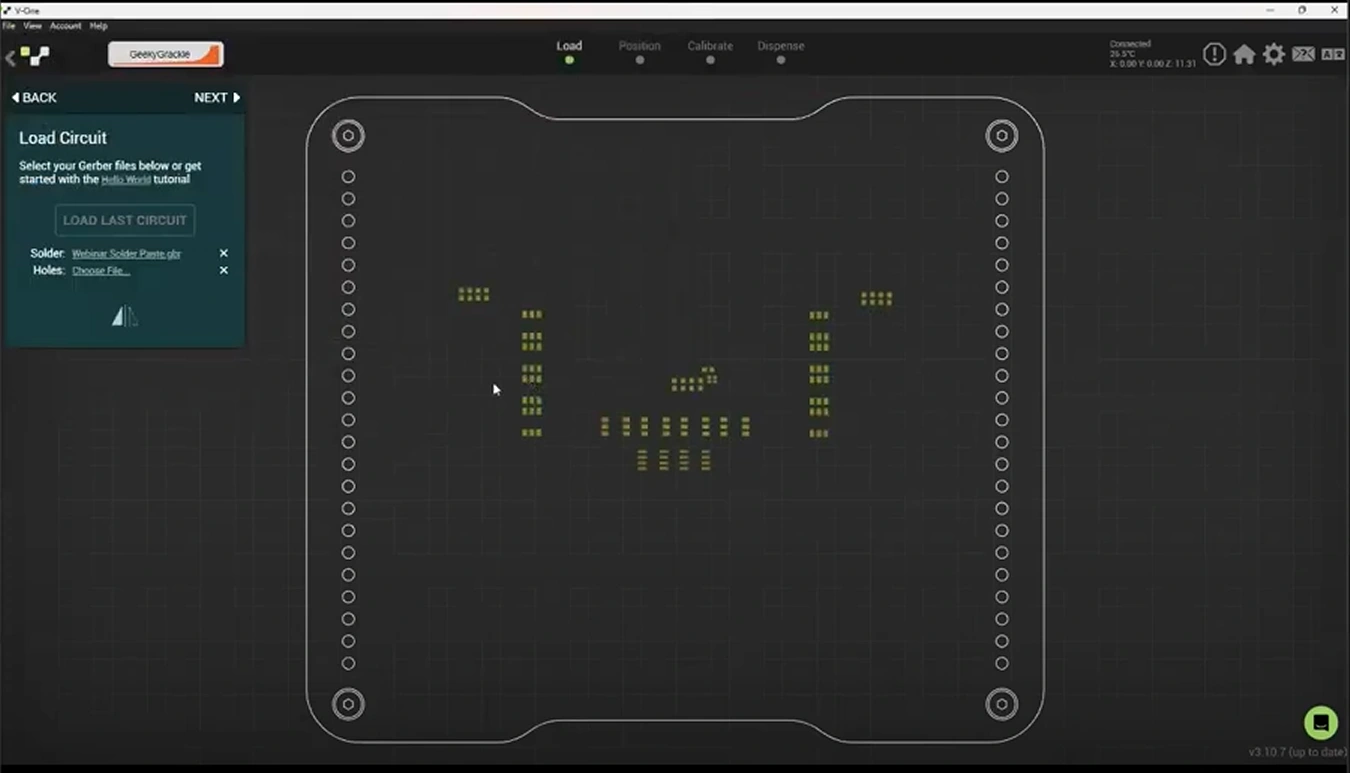
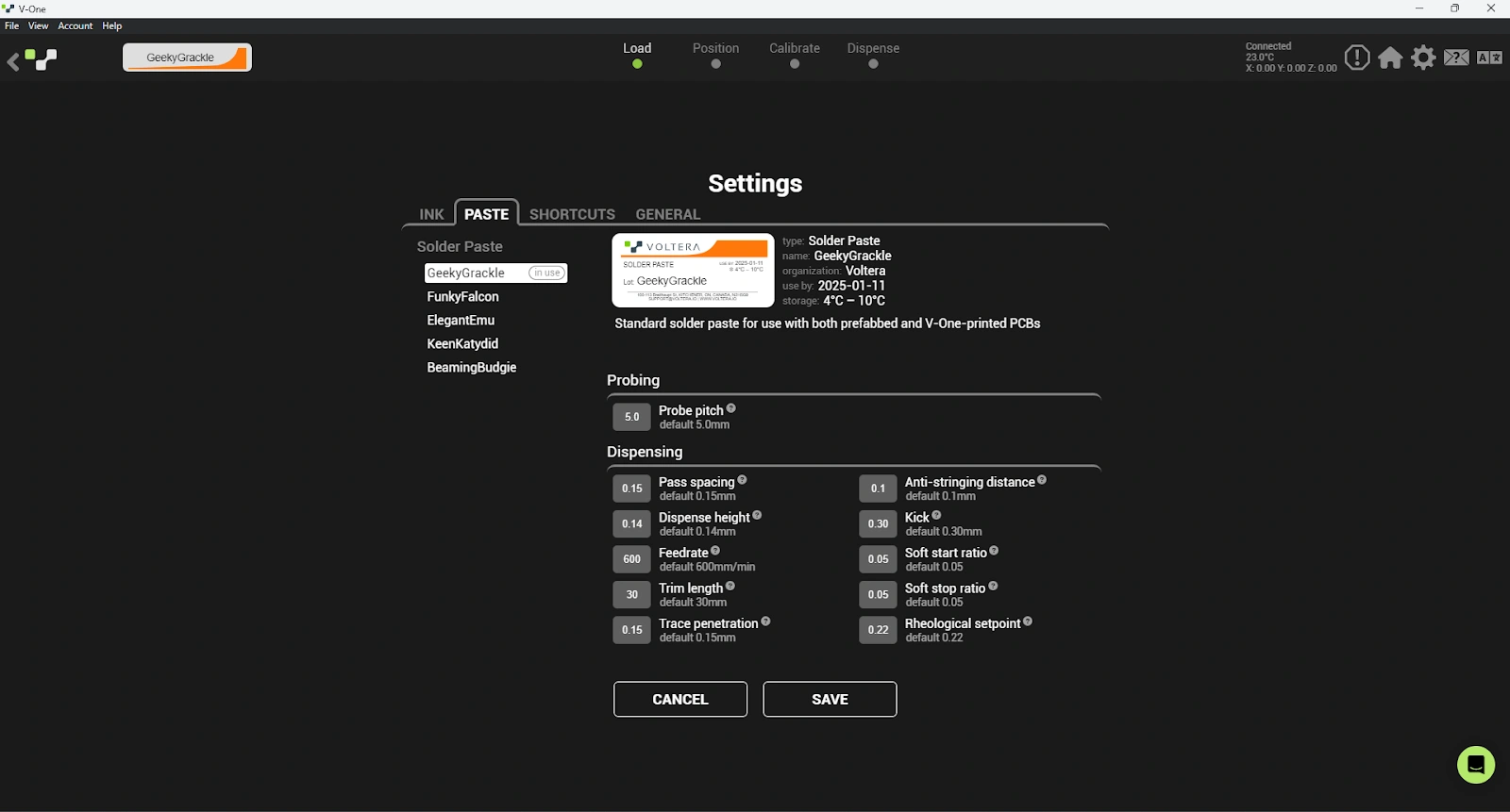
The V-One software is intuitive and guides you through every step of the PCB prototyping process, including printing, soldering, heating, and drilling. Since the PCB was prefabricated, we didn’t need to print conductive traces or drill through holes. Instead, we followed the SOLDER workflow.
The software prompted us to add the appropriate solder paste. We selected the T4 solder paste, and were then prompted to load a Gerber file. After loading the file, the software guided us through a quality check.
We cleaned the calibration switches using a few cotton swabs to remove any residual materials from previous use. Next, we clamped the PCB to the heated bed using four thumb screws and two clamps. After ensuring the PCB was securely fastened to the heated bed, we proceeded to probe the PCB.
Probing the PCB
To accurately dispense solder across the PCB surface, V-One first needed to generate a height map. We mounted the probe onto the carriage, and the software prompted us to align the features on the board with the features displayed in the software.
This process was semi-automatic. Our task was to select reference points and adjust the probe's position using the software’s arrow controls. Once we were satisfied with the alignment, V-One began mapping the board's height.

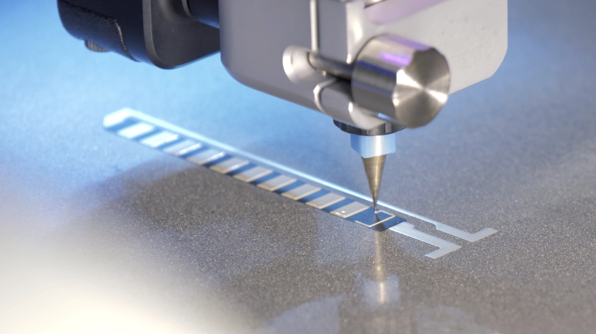
Dispensing solder paste on the PCB
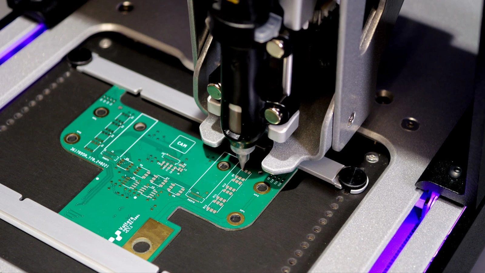
We inserted the solder paste into the dispenser slot, attached a disposable nozzle to the tip, and twisted the gear to prime the paste. Once there was a steady flow from the nozzle, we turned the gear back half a turn to slow down the flow and gently mounted the dispenser onto the carriage.
Next, we selected the features we wanted to print in the software, and the dispenser moved to the designated positions to begin dispensing solder paste. Throughout the process, it was easy to adjust the paste flow by clicking the + and - buttons in the software.
Populating the PCB and reflow
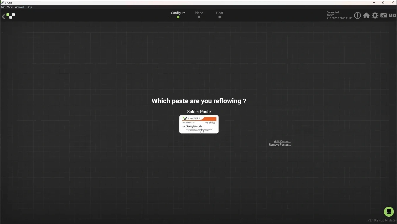
At this stage, the solder workflow was complete. We placed the components onto the board and selected HEAT > REFLOW > the T4 solder paste we used in the software. The heated bed started to heat the board automatically. The reflow process will last a few minutes where the solder paste is melted and cured, just like in a reflow oven. Once the board cooled down, we removed the board from V-one and our PCBA was completed.
Advice for dispensing solder paste
To ensure optimal performance, it is recommended to take the solder paste out of the refrigerator about 15 minutes before dispensing it onto the PCB. This acclimation period allows the paste to reach room temperature, improving its flow and consistency during application. Proper temperature adjustment helps prevent issues such as uneven dispensing or poor adhesion, which can result from changes in the paste's viscosity due to its thermal properties and temperature differences.
Conclusion
The board measures 100 mm × 83 mm. It took <7 minutes to complete the solder paste dispensing and about 24 minutes to complete the reflow step, which included heating up and cooldown time of V-One. After the reflow process, all the components were securely bonded to the PCB.
When we attached the camera to the board and mounted it to the bottom of NOVA’s module hub, we were able to view the work area clearly in NOVA’s software.
With precise control of the flow and flexible selection of features, V-One is an easy tool with intuitive processes for dispensing solder paste on factory fabricated PCBs.
As we continue to explore the possibilities of solder paste dispensing, we invite you to view the other projects we’ve completed.
Frequently asked questions
How do I choose the right solder paste for my electronic project?
You should select a solder paste based on alloy type, melting temperature, particle size (T-rating), and compatibility with your components and substrate. Low-temperature pastes (like Sn42Bi57.6Ag0.4) are ideal for heat-sensitive boards, while standard pastes suit most FR4 assemblies. For a comprehensive guide to choosing solder paste, check out Choosing the Right Solder Paste for Additive Electronics.
What’s the difference between lead-free solder paste and leaded solder paste?
Lead-free solder pastes use alloys such as bismuth-based formulations and have higher melting points (except low-temp Bi alloys). They are RoHS compliant and preferred for modern manufacturing. Leaded pastes (SnPb) melt at lower temperatures and are easier to reflow, but they are restricted in most commercial products due to environmental regulations.
How do I choose between dispensing and stencil printing?
Use dispensing when you need precision, small runs, rapid design changes, or selective deposition on a factory-fabricated PCB. It’s ideal for prototyping environments. Choose stencil printing for high-volume PCB assemblies where throughput matters most. Stencils deliver consistent paste deposits but require additional tooling.
Can I dispense solder paste on non-flat or flexible substrates?
Yes. Dispensing is well suited for substrates that are slightly uneven or flexible, as long as the system can probe the surface and generate an accurate height map. For highly flexible films, the substrate must be secured firmly to ensure accurate Z-height control and avoid smearing or misalignment.
How do I store and handle solder paste properly?
Store solder paste refrigerated in a sealed container and let it warm to room temperature for 10-20 minutes before use. Avoid repeated temperature cycling, keep containers closed to prevent drying, and follow the manufacturer’s shelf-life guidelines. Proper handling preserves viscosity, prevents separation, and ensures reliable dispensing and reflow.
Printing multilayer flexible, stretchable, and conformable electronics?
NOVA’s Plan feature makes it easy.