White paper
Printing a Control Board for a Line Following Robot with Silver Ink on FR1
Prototyping robotics offers great potential in electronics education, providing a fun way to learn about sensors and motion control. Building a line-following robot can be both educational and practical, with applications in automated delivery systems and robot racing competitions.

- V-One PCB printer
- Bambu Lab 3D printer
- Nordson EFD 7018395 dispensing tip
- Walfront infrared proximity sensors
- Texas Instruments L293DNE motor driver
- Texas Instruments NE555DR timers
- LEDs
- Rivets
Project overview
Purpose
The goal of this project was to prototype a circuit board that controls a line-following robot, using a simple design that could be used to teach electronics in a hands-on way.
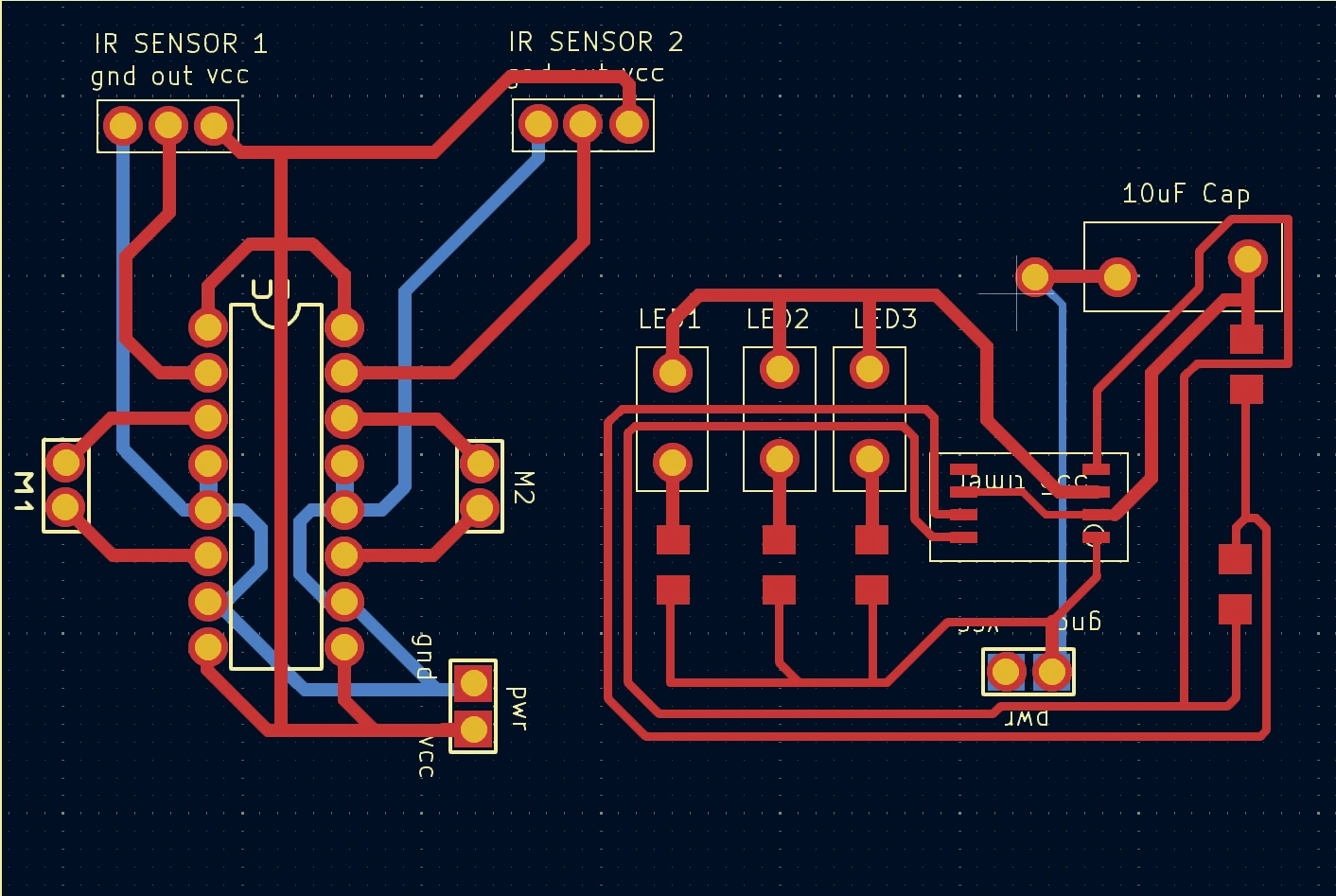
Design
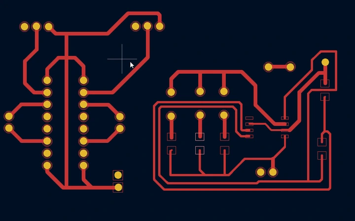
For the control board, we separated the ground traces and other signal traces on opposite sides of the FR1 board, with through-holes to mount key components like the 16-pin L293DNE motor driver.
These through-holes also serve to accommodate other components such as LEDs, infrared proximity sensors, and motors, which could not be surface-mounted due to their size and functional requirements.
We divided the robot’s main body into small parts and printed them with a 3D printer.
Desired outcome
Once connected to power, a 9V battery, the assembled robot should be able to distinguish its designated paths from the background and navigate along the paths, making turns as needed.
Functionality
By using infrared proximity sensors, motors, and a motor driver, our design enabled the robot to move along the yellow tape on the black floor and navigate corners, all without relying on a microcontroller or onboard code, which would have introduced unnecessary complexity.
For the purpose of this project, we did not require a specific travel speed. However, the design can be customized for other activities, such as robot racing or obstacle avoidance challenges by reducing the overall weight of the robot, adjusting the configuration of sensors, or choosing high speed rated motors.
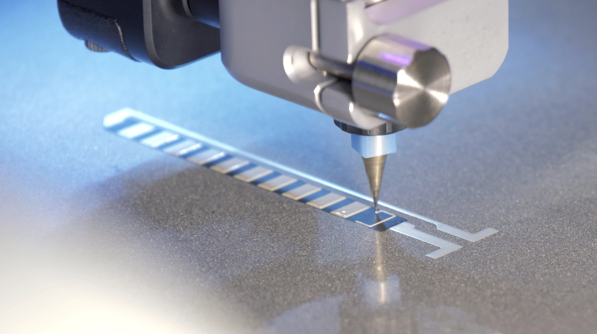
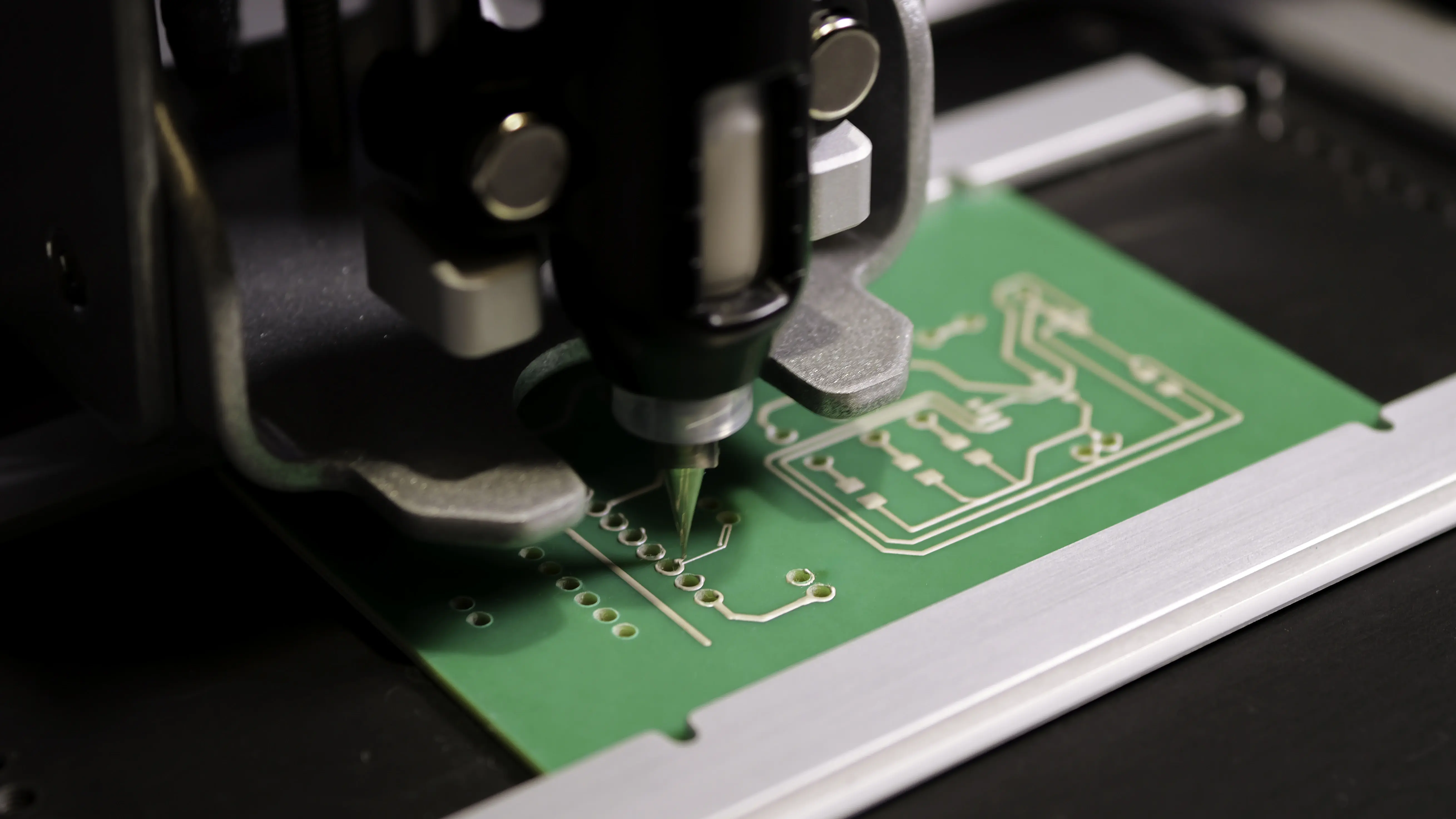
Printing the control board
Printing the front side
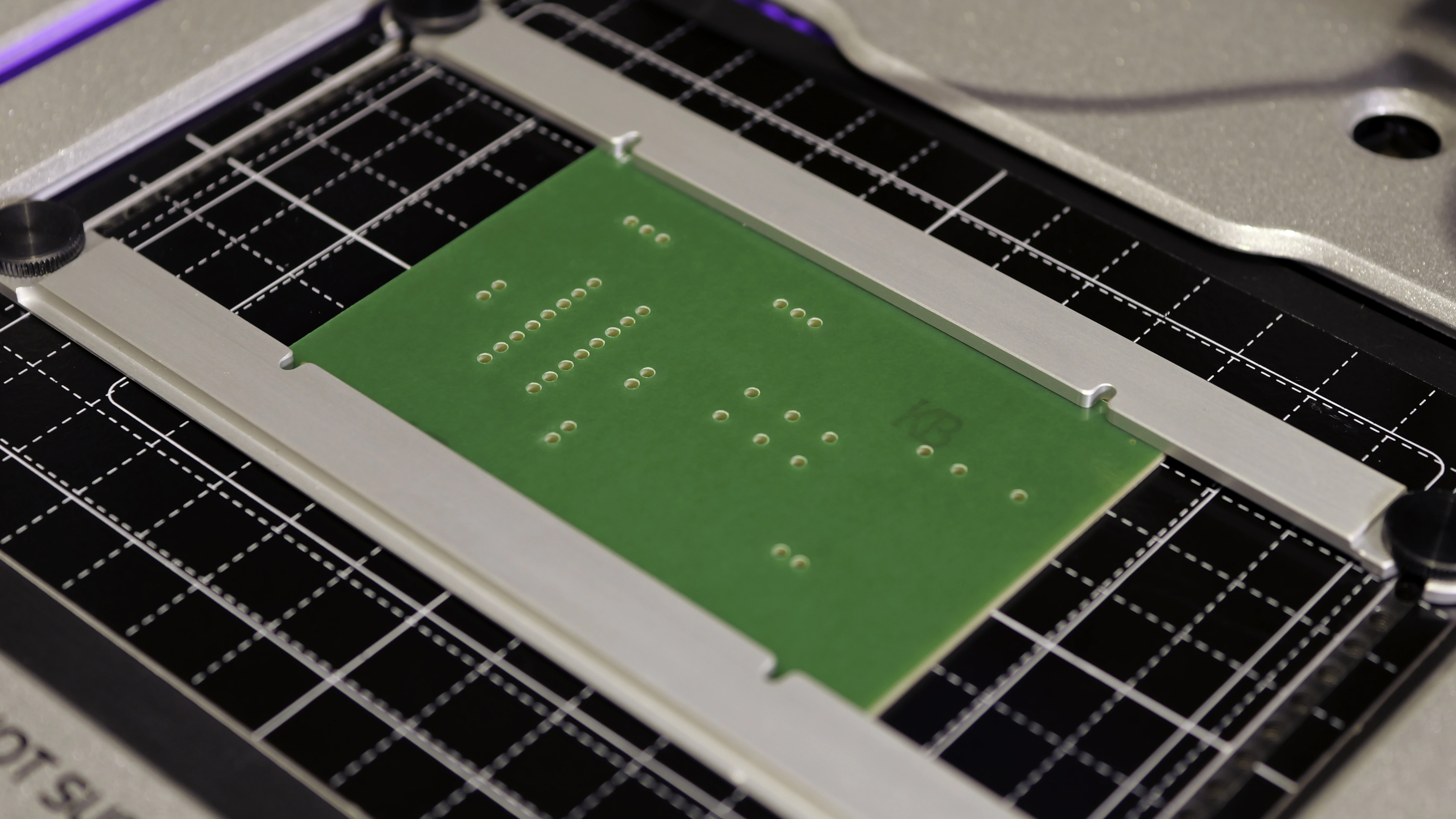
Before dispensing the silver ink, we drilled 39 through-holes with a diameter of 1.6 mm on the FR1 board using V-One.
On the front side of the board, two infrared proximity sensors detect the paths and send signals to the motor driver, which controls the robot's movement by turning the motors on or off.
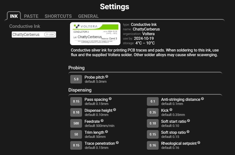
| Ink | Voltera Conductor 3 silver ink |
| Substrate | 2" x 3" FR1 board |
| Nozzle type | Nordson EFD 7018395 200 μm dispensing tip |
| Probe pitch | 5 mm |
| Probe time | 15 minutes |
| Print time | 10 minutes |
| Cure time and temperature | 90°C for 5 minutes, and then 170°C for 15 minutes |
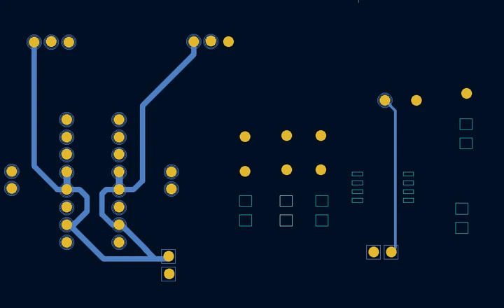
Printing the back side
The back side of the board consists of traces that connect to the ground pins of the components and complete the circuit.
| Ink | Voltera Conductor 3 silver ink |
| Substrate | 2" x 3" FR1 board |
| Nozzle type | Nordson EFD 7018395 200 μm dispensing tip |
| Probe pitch | 5 mm |
| Probe time | 10 minutes |
| Print time | 5 minutes |
| Cure time and temperature | 90°C for 5 minutes, and then 170°C for 15 minutes |
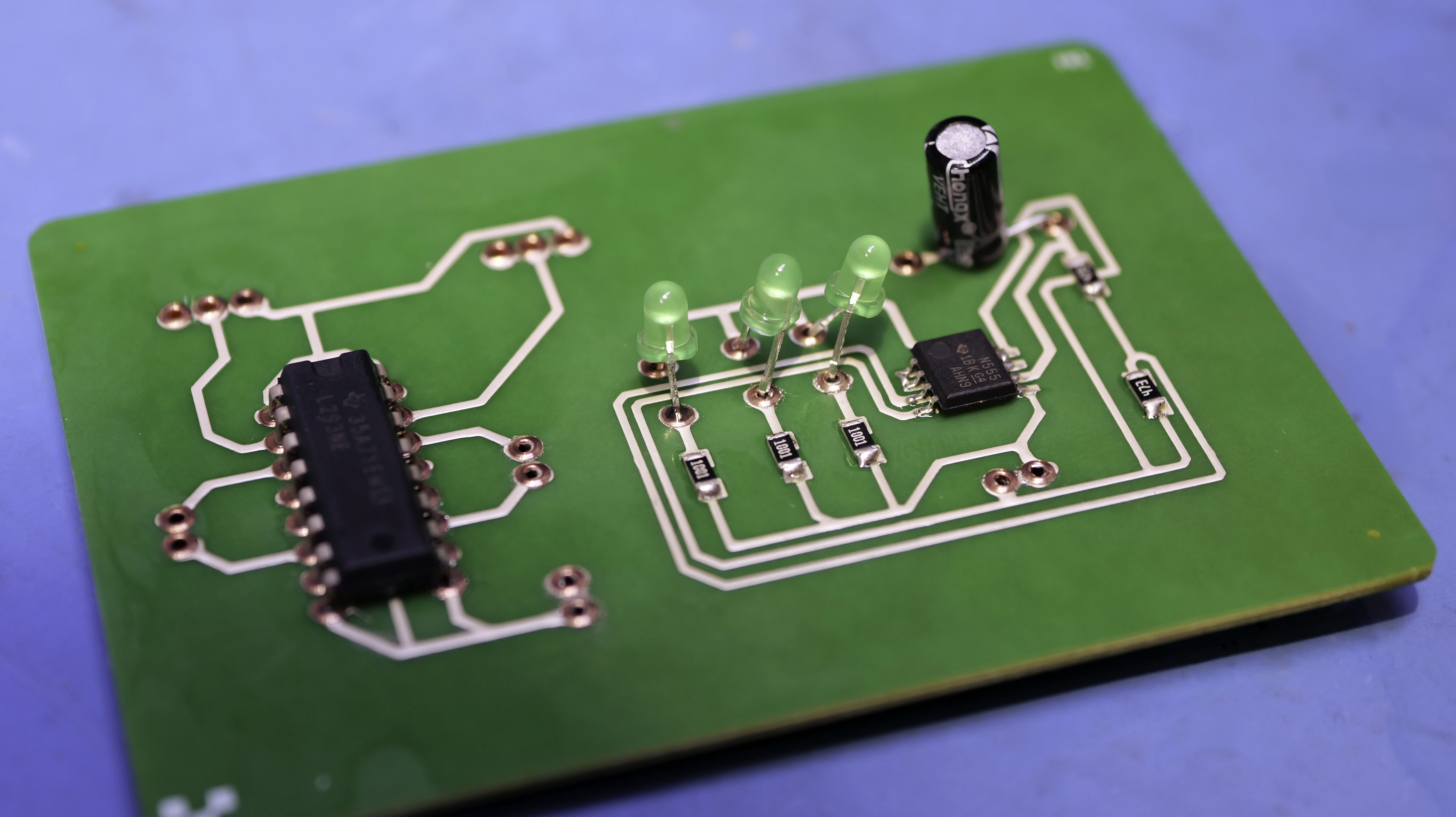
Post processing the control board
When both sides were complete, we inserted rivets into the through-holes and dispensed solder paste for resistors and the NE555 timer using V-One’s built-in solder paste dispensing workflow. We then populated the components and manually soldered the motor driver, capacitor, motors, infrared proximity sensors, and LEDs.
3D printing the main body
To house the control board and serve as the robot’s movement platform, we designed a main body divided into four parts. These parts were 3D printed using PLA filament:
- Two wheels
- Two motor brackets
- A case
- A lid
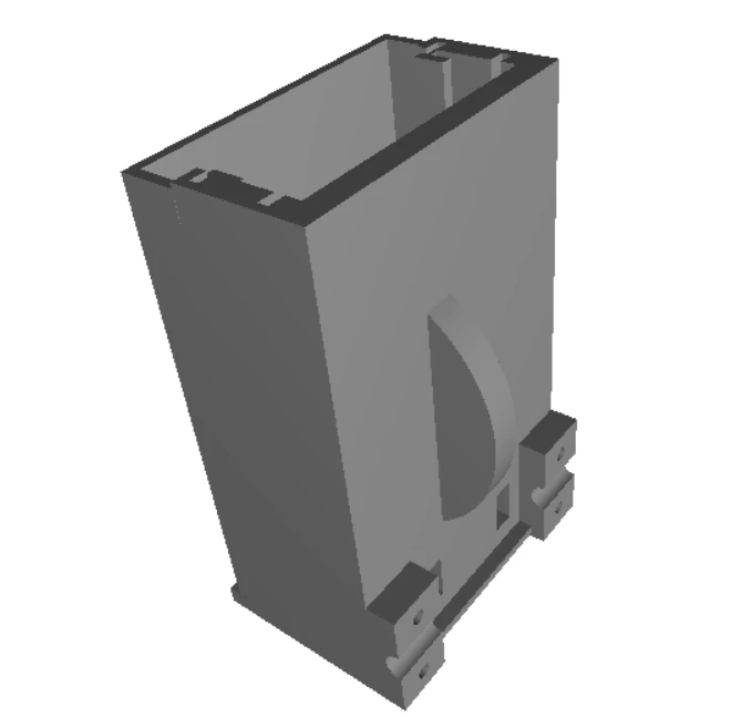
We then put the control board into the case and assembled the parts.
Challenges and advice
Soldering issues
Conductive ink, when applied to FR1, can sometimes adhere less robustly compared to traditional copper traces on a PCB. This makes it prone to being lifted off the board during soldering if excessive heat, pressure, or mechanical stress is applied.
To improve solderability, we lowered the curing temperature of the ink. This adjustment enhanced wettability, allowing solder to adhere more effectively to conductive pads, especially for sensitive connections and larger components.
Conclusion
This project demonstrated that a double-sided control board printed on FR1 with silver ink can successfully drive a line-following robot. Once powered by a 9V battery, the assembled robot was able to distinguish its designated path from the background and navigate along it, including making turns, validating both the circuit design and the overall system concept.
Beyond demonstrating functional performance, the project also highlights how PCB prototyping and robotics can be combined in a hands-on format to teach core concepts in sensing, motion control, and circuit assembly.
If you’re interested in exploring other PCB prototyping projects we have completed, take a look at:
Frequently asked questions
How does a line-following robot work?
A line-following robot uses sensors to detect contrast between a path (such as a black or colored line) and the surrounding surface. Based on sensor readings, the control circuit adjusts motor behavior like speeding up, slowing down, or stopping individual motors to keep the robot aligned with the line. In this project, the logic is implemented entirely in hardware, without a microcontroller, using sensors, timers, and a motor driver.
What sensors are best for line-following robots?
Infrared (IR) proximity or reflectance sensors are the most common choice. They are inexpensive, easy to interface, and effective at distinguishing light and dark surfaces. Other options include photodiodes, phototransistors, or camera-based vision systems, but IR sensors strike a good balance between simplicity, reliability, and cost—especially for educational projects.
How do infrared sensors detect a black line on a white surface?
IR sensors emit infrared light and measure how much of it is reflected back. Light-colored surfaces reflect more IR light, while dark surfaces absorb more, resulting in a weaker reflected signal. By comparing the sensor output to a threshold, the circuit can determine whether the robot is over the line or the background and adjust motor control accordingly.
What microcontroller should I use?
For this project, no microcontroller is required as the robot operates using discrete components, which simplifies the design and makes it ideal for learning core electronics concepts. If you want to add features like programmable behavior, wireless control, or advanced sensing, a microcontroller such as Arduino (beginner-friendly), ESP32 (Wi-Fi/Bluetooth enabled), or Raspberry Pi (for vision-based control) can be integrated into an expanded design.
Printing multilayer flexible, stretchable, and conformable electronics?
NOVA’s Plan feature makes it easy.